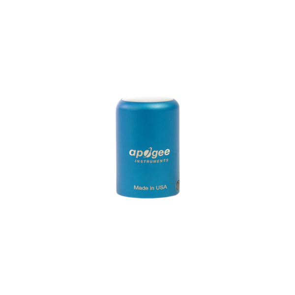
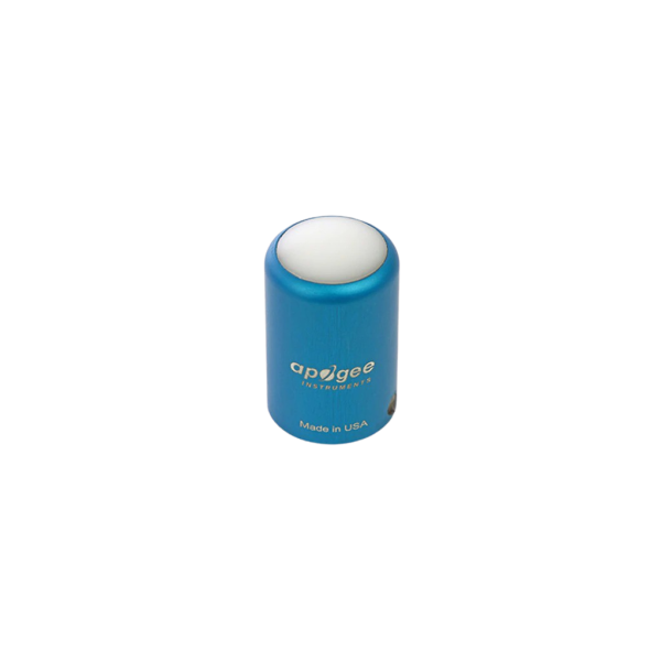
Apogee SQ-520 Full Spectrum Quantum Sensor (USB)
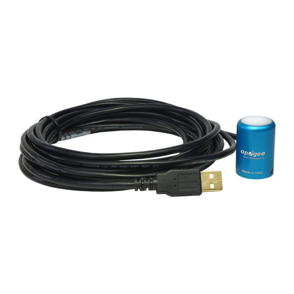
Full-Spectrum Smart Quantum Sensor
- 400 - 750 nm
- can be connected directly to a Computer via USB
- data recordings in real-time
- capable of storing 10.000 measurements thanks to internal memory
- Manufacturer:Apogee Instruments
- SKU:1507129
The new SQ-520 full-spectrum, smart quantum sensor can be connected directly to a computer (Windows or macOS X) via USB for taking spot measurements or graphing and datalogging real-time PPFD using the included software.
The sensor can also act as a stand-alone PAR datalogger by simply connecting it to most standard 5 V DC USB power plugs. Internal memory within the sensor head is capable of storing 10,000 user-specified periodic measurements that can be downloaded as a CSV file to a computer for analysis.
Full-spectrum Quantum SensorMeasure photosynthetically active radiation, PAR, in µmol m-2 s-1.
Apogee Instruments‘ quantum sensors provide accurate and cost-effective measurement of photosynthetically active radiation (PAR) from all light sources used to grow plants and corals.
Spectral ResponseThe full-spectrum quantum sensor has a spectral range of 389 to 692 ± 5 nm. The improved spectral response increases the accuracy of LED measurements.
Accurate, Stable MeasurementsSensors are cosine-corrected to maintain their accuracy when radiation comes from low zenith angles. The sensors measure PPFD with a cosine response accurate within ± 5 % at 75° zenith angle. Long-term non-stability determined from multiple replicate quantum sensors in accelerated aging test and field conditions is less than 2 % per year.
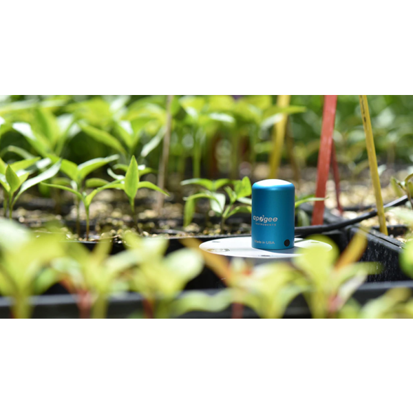
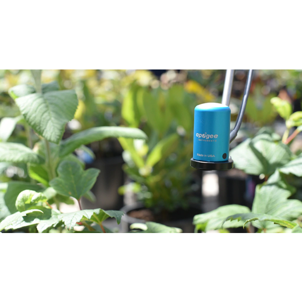
Typical ApplicationsPPFD measurements over plant canopies in outdoor environments, greenhouses, and growth chambers, and reflected or under canopy (transmitted) PPFD measurements in the same environments. Quantum sensors are also used to measure PPFD in aquatic environments, including salt water aquariums where corals are grown.
Rugged, Self-cleaning HousingPatented domed shaped sensor head (diffuser and body) facilitate runoff of dew and rain to keep the sensor clean and minimize errors caused by dust blocking the radiation path. Sensors are housed in a rugged anodized aluminum body and electronics are fully potted.
Ideal for Measurements in Air and UnderwaterApogee quantum sensor are calibrated to make absolute PPFD measurements in air. The waterproof sensors can be used to make absolute PPFD measurements underwater by applying an immersion effect correction factor, the SQ-420, SQ-520, MQ-210, and MQ-510 already apply the correction factor. For details on making underwater measurements, please refer to Underwater PAR Measurements.
CalibrationTo ensure accuracy each sensor is carefully calibrated in controlled conditions and traceable to NIST reference standards. The full-spectrum sensors are pre-calibrated for all light sources.
MountingThe AL-120 Solar Mounting Bracket with Leveling Plate facilitates mounting the sensor to a mast or pipe. The AL-100 Solar Sensor Leveling Plate is designed to level the sensor while sitting an a flat surface or mounting to a surface.
Output OptionsAvailable in multiple analog output option including 0 to 40 mV, 0 to 2.5 V, and 0 to 5 V. Additionally, a digital “smart“ sensor that uses USB cummunication and custom Software to interface directly to a computer is available. Sensors are also available attached to a hand-held meter with digital readout.
High Quality CablePigtail-lead sensors feature an IP68, marine-grade stainless steel cable connector approximately 30 cm from the head to simplify sensor removal for maintenance and recalibration. Cable is shielded-twisted pair wire with a TPR jacket for high water resistance, UV stability, and flexibility in cold conditions.
Deployment and Installation
Mount the sensor to a solid surface with the nylon mounting screw provided. To accurately measure PPFD incident on a horizontal surface, the sensor must be level. An Apogee Instruments model AL-100 leveling plate is recommended for this purpose. To facilitate mounting on a cross arm, an Apogee Instruments model AM-110 mounting bracket is recommended.
To minimize azimuth error, the sensor should be mounted with the cable pointing toward true north in the northern hemisphere or true south in the southern hemisphere. Azimuth error is typically less than 0.5 %, but it is easy to minimize by proper cable orientation.
In addition to orienting the cable to point toward the nearest pole, the sensor should also be mounted such that obstructions (e.g., weather station tripod/tower or other instrumentation) do not shade the sensor. Once mounted, the green cap should be removed from the sensor. The green cap can be used as a protective covering for the sensor when it is not in use.
Cable Connectors
Apogee started offering in-line cable connectors on some bare-lead wire sensors in March 2018 to simplify the process of removing sensors from installations for recalibration (the entire cable does not have to be removed from the station and shipped with the sensor). The ruggedized M8 connectors are rated IP68, made of corrosion-resistant marine-grade stainless-steel, and designed for extended use in harsh environmental conditions.
Instructions
Pins and Wiring Colors: All Apogee connectors have six pins, but not all pins are used for every sensor. There may also be unused wire colors inside the cable. To simplify connection to a measurement device, the unused pigtail lead wire colors are removed. If a replacement cable is required, please contact Apogee directly to ensure ordering the proper pigtail configuration.
Alignment: When reconnecting a sensor, arrows on the connector jacket and an aligning notch ensure proper orientation. A reference notch inside the connector ensures proper alignment before tightening.
Disconnection for extended periods: When disconnecting the sensor for an extended period of time from an installation, protect the remaining half of the connector still on the station from water and dirt with electrical tape or other method. When sending sensors back for recalibration, only send the section of cable that is hard-wired to the sensor. The section of cable with the pigtail is not required.
Tightening: Connectors are designed to be firmly finger-tightened only. There is an O-ring inside the connector that can be overly compressed if a wrench is used. Pay attention to thread alignment to avoid cross-threading. When fully tightened, one to two threads may still be visible.
WARNING: Do not tighten the connector by twisting the black cable, only twist the metal connector.
Operation and Measurements
Connect the sensor to a measurement device (meter, datalogger, controller) capable of measuring and displaying or recording a millivolt signal (an input measurement range of approximately 0 to 25 mV is required to cover the entire range of PPFD from the sun). In order to maximize measurement resolution and signal-to-noise ratio, the input range of the measurement device should closely match the output range of the quantum sensor. DO NOT connect the sensor to a power source. The sensor is self-powered and applying voltage will damage the sensor.
VERY IMPORTANT: Apogee changed all wiring colors of our bare-lead sensors in March 2018 in conjunction with the release of inline cable connectors on some sensors. To ensure proper connection to your data device, please note your serial number or if your sensor has a stainless-steel connector 30 cm from the sensor head then use the appropriate wiring configuration from the manual (available for download).
Sensor Calibration
Apogee un-amplified full spectrum quantum sensors, model SQ-500, have a standard PPFD calibration factor of exactly:
100.0 µmol m-2 s -1 per mV
Multiply this calibration factor by the measured voltage to convert sensor output to PPFD in units of µmol m-2 s -1 :
Calibration Factor (100 µmol m-2 s -1 per mV) * Sensor Output Signal (mV) = PPFD (µmol m-2 s -1 ) 100 * 20 = 2000
Full sunlight yields a PPFD on a horizontal plane at the Earth’s surface of approximately 2000 µmol m-2 s -1 . This yields an output signal of 20 mV. The signal is converted to PPFD by multiplying by the calibration factor of 100.0 µmol m-2 s -1 per mV.
Software and Installation
The most recent version of ApogeeConnect software can be downloaded here. After double-clicking on the installation file, all you have to do is to agree to the terms of use and press "Continue" until the installation is completed. You have the option to change the Installation path by clicking on "Change Install Location".
| Weight: | 100 g (with 5 m of lead wire) |
| Spectral Range: | 389 to 692 nm ± 5 nm (wavelengths where response is greater than 50 % of maximum) |
| Long-term Drift (Non-stability): | Less than 2 % per year |
| Response Time: | Software updates every second |
| Spectral Selectivity: | Less than 10 % from 412 to 682 nm ± 5 nm |
| Operating Environment: | -40° to 70° C; 0 to 100 % relative humidity; can be submerged to depths of 30 m |
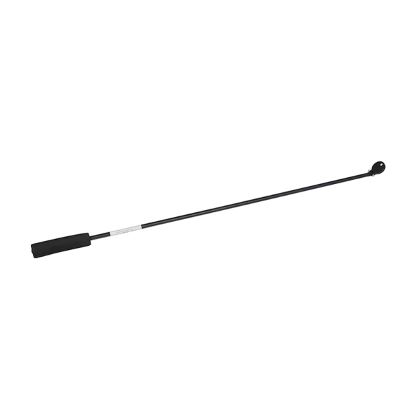
| Sensor Dimensions: | 24 mm diameter, 37 mm height |
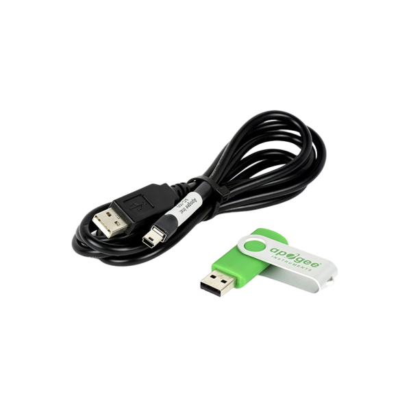
| Cable: | USB Cable 4,5 m |