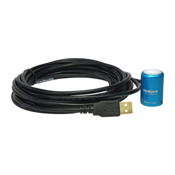
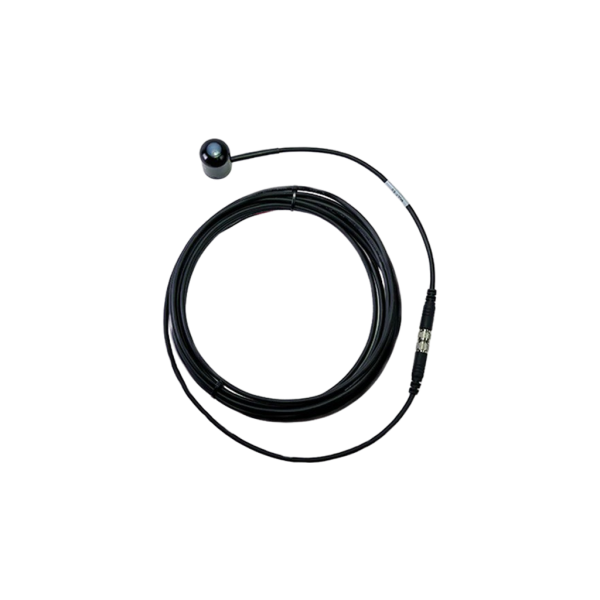
Apogee SQ-100X-SS Sun calibration quantum sensor, 5 m cable length with connector
Analog Quantum sensor for PPFD measurements
- self-supplying, with a self-cleaning housing design
- simple connection to data logger
- for Outdoor Environments, greenhouses and growth chambers
- Manufacturer:Apogee Instruments
- SKU:13145
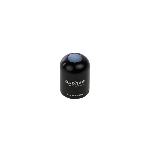
The SQ-100X-SS is a self-powered, analog original quantum sensor with a 0 to 250 mV output. The sensor features a rugged, self-cleaning sensor housing design, and high-quality cable terminating in pre-tinned pigtail leads for easy connection to dataloggers and controllers. Typical applications include PPFD (Photosynthetic Photon Flux Density) measurement over plant canopies in outdoor environments, greenhouses, and growth chambers, and reflected or under-canopy (transmitted) PPFD measurements in the same environments.
Quantum sensors are also used to measure PAR (Photosynthetically Active Radiation)/PPFD in aquatic environments, including salt water aquariums where corals are grown. Sensor includes IP68 marine-grade stainless-steel cable connector 30 cm from head to simplify sensor removal and replacement for maintenance and recalibration.
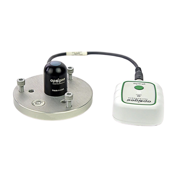
The analog version of this sensor (SQ-100X-SS) comes with the inline cable connector placed 30 cm from the sensor head for either standard use as a long-cable pigtail sensor, or for use with Apogee Instruments microCache Bluetooth Micro Logger by unscrewing the connector, discarding the long section of cable and then screwing the sensor to the mating connector on the microCache.
Mount the sensor to a solid surface with the nylon mounting screw provided to prevent galvanic corrosion. To accurately measure PPFD incident on a horizontal surface, the sensor must be level. An Apogee Instruments model AL-100 Leveling Plate is recommended to level the sensor when used on a flat surface or being mounted to surfaces such as wood. To facilitate mounting on a mast or pipe, the Apogee Instruments model AL-120 Solar Mounting Bracket with Leveling Plate is recommended.
Important: Only use the nylon screw provided when mounting to insulate the non-anodized threads of the aluminum sensor head from the base to help prevent galvanic corrosion. For extended submersion applications, more insulation may be necessary. Contact Apogee tech support for details.
To minimize azimuth error, the sensor should be mounted with the cable pointing toward true north in the northern hemisphere or true south in the southern hemisphere. Azimuth error is typically less than 1 %, but it is easy to minimize by proper cable orientation.
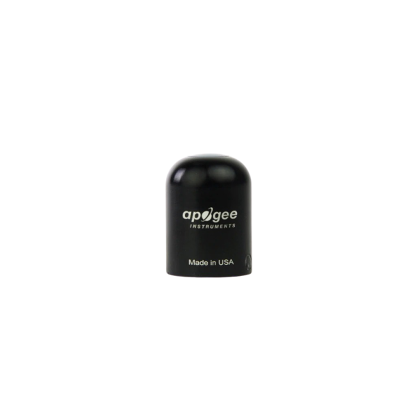
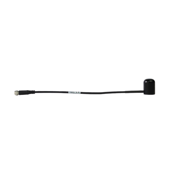
In addition to orienting the cable to point toward the nearest pole, the sensor should also be mounted such that obstructions (e.g., weather station tripod/tower or other instrumentation) do not shade the sensor. Once mounted, the green cap should be removed from the sensor. The green cap can be used as a protective covering for the sensor when it is not in use.
Cable connectors
Apogee sensors offer cable connectors to simplify the process of removing sensors from weather stations for calibration (the entire cable does not have to be removed from the station and shipped with the sensor).
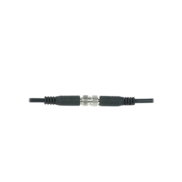
The ruggedized M8 connectors are rated IP68, made of corrosion-resistant marine-grade stainless-steel, and designed for extended use in harsh environmental conditions. Inline cable connectors are installed 25 cm from the head.
Pins and Wiring Colors: All Apogee connectors have six pins, but not all pins are used for every sensor. There may also be unused wire colors inside the cable. To simplify datalogger connection, Apogee removes the unused pigtail lead colors at the datalogger end of the cable.
If a replacement cable is required, please contact Apogee directly to ensure ordering the proper pigtail configuration.
Alignment: When reconnecting a sensor, arrows on the connector jacket and an aligning notch ensure proper orientation. A reference notch inside the connector ensures proper alignment before tightening.
Disconnection for extended periods: When disconnecting the sensor for an extended period of time from a station, protect the remaining half of the connector still on the station from water and dirt with electrical tape or other method. When sending sensors in for calibration, only send the short end of the cable and half the connector.
Tightening: Connectors are designed to be firmly finger-tightened only. There is an o-ring inside the connector that can be overly compressed if a wrench is used. Pay attention to thread alignment to avoid cross-threading. When fully tightened, 1 - 2 threads may still be visible.
Operation and Measurement
Connect the sensor to a measurement device (meter, datalogger, controller) capable of measuring and displaying or recording a millivolt signal (an input measurement range of approximately 0 - 500 mV is required to cover the entire range of PPFD from the sun). In order to maximize measurement resolution and signal-to-noise ratio, the input range of the measurement device should closely match the output range of the quantum sensor. DO NOT connect the sensor to a power source. The sensor is self-powered and applying voltage will damage the sensor.
VERY IMPORTANT: Apogee changed the wiring colors of all their bare-lead sensors in March 2018 in conjunction with the release of inline cable connectors on some sensors. To ensure proper connection to your data device, please note your serial number or if your sensor has a stainless - steel connector 30 cm from the sensor head then use the appropriate wiring configuration listed in the manual (available for download). With the switch to connectors, Apogee also changed to using cables that only have 4 or 7 internal wires. To make their various sensors easier to connect to your device, Apogee clip off any unused wire colors at the end of the cable depending on the sensor. If you cut the cable or modify the original pigtail, you may find wires inside that are not used with your particular sensor. In this case, please disregard the extra wires and follow the color-coded wiring guide provided.
Sensor Calibration
All Apogee un-amplified quantum sensor models (SQ-100 and SQ-300 series) have a standard PPFD calibration factor of exactly:
5.0 μmol m-2 s-1 per mV
Multiply this calibration factor by the measured mV signal to convert sensor output to PPFD in units of
μmol m-2 s-1:
Calibration Factor (5.0 μmol m-2 s-1 per mV) * Sensor Output Signal (mV) = PPFD (μmol m-2 s-1)
5.0 * 400 = 2000
Spectral Errors and Yield Photon Flux Measurements
Apogee quantum sensors are calibrated to measure PPFD for either sunlight or electric light. The difference between the calibrations is 12 %. A sensor calibrated for electric lights (calibration source is T5 cool white fluorescent lamps) will read approximately 12 % low in sunlight.
In addition to PPFD measurements, Apogee SQ series quantum sensors can also be used to measure yield photon flux density (YPFD): photon flux density weighted according to plant photosynthetic efficiency (McCree, 1972) and summed. YPFD is also expressed in units of μmol m-2 s-1, and is similar to PPFD, but has been reported to be more closely correlated to photosynthesis than PPFD in some studies. PPFD is usually measured and reported because the PPFD spectral weighting function (equal weight given to all photons between 400 and 700 nm; no weight given to photons outside this range) is easier to define and measure, and as a result, PPFD is widely accepted. The calibration factor for YPFD is 4.50 and 4.45 μmol m-2 s-1 per mV for sunlight and electric light measurements, respectively.
The weighting functions for PPFD and YPFD are shown in the graph below, along with the spectral response of Apogee SQ series quantum sensors. The closer the spectral response matches the defined PPFD or YPFD spectral weighting functions, the smaller spectral errors will be. The table below provides spectral error estimates for PPFD and YPFD measurements from light sources different than the calibration source. The method of Federer and Tanner (1966) was used to determine spectral errors based on the PPFD and YPFD spectral weighting functions, measured sensor spectral response, and radiation source spectral outputs (measured with a spectroradiometer). This method calculates spectral error and does not consider calibration, cosine, and temperature errors.
Underwater Measurements and Immersion Effect
When a quantum sensor that was calibrated in air is used to make underwater measurements, the sensor reads low. This phenomenon is called the immersion effect and happens because the refractive index of water (1.33) is greater than air (1.00). The higher refractive index of water causes more light to be backscattered (or reflected) out of the sensor in water than in air (Smith,1969; Tyler and Smith,1970). As more light is reflected, less light is transmitted through the diffuser to the detector, which causes the sensor to read low. Without correcting for this effect, underwater measurements are only relative, which makes it difficult to compare light in different environments.
The SQ-100 and SQ-300 series sensors have an immersion effect correction factor of 1.08. This correction factor should be multiplied to measurements made underwater.
Further information on underwater measurements and the immersion effect can be found here.
| Weight: | 90 g (with 5 m of lead wire) |
| Spectral Range: | 370 nm to 650 nm (wavelengths where response is greater than 50 % of maximum) |
| Long-term Drift (Non-stability): | Less than 2 % per year |
| Response Time: | Less than 1 ms, ± 5 % at 75˚ zenith angle |
| Spectral Selectivity: | Less than 10 % from 469 to 655 nm |
| Operating Environment: | -40° to 60° C; 0 to 100 % relative humidity; can be submerged in water up to depths of 30 m |
| Sensor Dimensions: | 24 mm Diameter, 33 mm height |
| Cable: | 5 m of shielded, twisted-pair wire with TPR jacket (high water resistance, high UV stability, flexibility in cold conditions) |
| For extended underwater use, please call Apogee direct to order your sensor without the inline connector. |